
Online Monitoring of Drilling Mud Density: Analysis of Material, Range, and Calibration Parameters of Tuning Fork Densitometers
Leave a message
Previously, I took on a drilling site project where the client wanted to install a densitometer on the mud return pipeline at the wellhead to monitor the density changes of the returning mud in real time. The site engineer had previously used a differential pressure type, but the mud contained a lot of cuttings, causing the pressure tubes to frequently clog and require disassembly and cleaning. Additionally, the signal lagged when density fluctuated, which made the driller feel uncertain. Therefore, this time they wanted to switch to an instrument that could be directly inserted into the pipeline without clogging and operating smoothly.
I first inquired about the mud details. It was water-based mud with high solids content, considerable viscosity, and contained salts and sulfur, which could corrode ordinary stainless steel. The maximum density could reach around 2.8, and the returned temperature at the wellhead was around 70–80°C. The pipeline was DN80, the site was in explosion-proof Zone 2, power supply was 24V, and the signal needed to go directly into the driller room PLC.
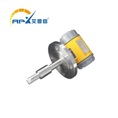
Considering these working conditions, I recommended a tuning fork densitometer. It has no pressure ports or moving parts, so large cuttings cannot get stuck, and daily maintenance only requires occasional cleaning of dried mud on the fork surface. For materials, the fork and probe must be 316L for pitting corrosion resistance and erosion resistance; the flange can be 304 since it does not directly contact the flowing mud. The client approved.
Next, we determined the specific parameters. Connection size according to DN80 flange, national standard. The probe insertion length must ensure that the fork is in the mainstream of the fluid, avoiding the pipe wall effect, finally deciding on a probe length below the flange of 400mm. The measurement range is 0–3 g/cm³, covering both light and heavy mud. The output is two-wire 4–20mA, directly interfacing with the PLC. The client required accuracy in the actual operating range of 1.0–1.5, and we promised factory calibration at these three points with standard fluids. With mud temperatures of 80°C, temperature compensation was necessary. Additionally, due to high mud viscosity and concern about material accumulation affecting readings, I increased the internal viscosity parameter of the instrument to reduce sensitivity to changes in viscous force on vibration frequency, resulting in a more stable display.
The finalized solution: DN80 flange (304 material), probe length 400mm (316L), range 0–3, two-wire 4–20mA, 24V power supply, with local display, calibration points 1.0/1.2/1.5, temperature compensation 80°C. The product was manufactured according to this configuration. Installation and commissioning on site went smoothly. After more than a month of use, the client reported that the data was timely, subtle changes in mud density could be observed, and after removal, the fork only had a thin layer of mud, easily rinsed, basically worry-free. This project made me realize that once you thoroughly understand the working conditions, correlate the instrument principle with the on-site pain points, the parameter selection and product choice naturally become clear.